Last week I ran a pretty straightforward lab:
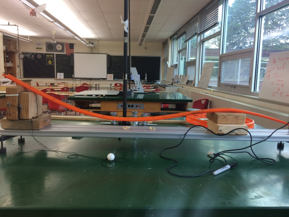
- Put 120cm of hot wheel track into a design of your choosing
- Run a ball down the track
- Record velocity with a photogate
- Repeat at 10-12 locations
- Plot the energy curves.
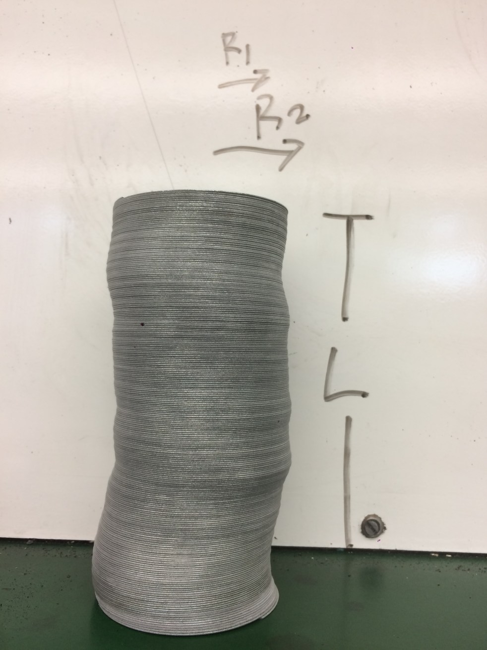
- Plot Translational vs Rotational Kinetic energies and find the rotational inertia constant.
Students should see a transfer of kinetic and potential energy which makes sense. Of course, students should also expect to see a decreasing total energy curve because of friction constantly taking energy from the system.
I had two fun surprises I got to incorporate:
- The shape of the TME curve
Inevitably this curve had a particularly sharp drop off at one moment in time. I had students sketch their tracks on their whiteboards in addition to their lab results. 
 Do you notice anything? The largest drop off in TME corresponds to the moment where the ball is at the bottom of the hill. This serves as a great review of work and circular motion. Frictional force, as we know, is dependant on normal force. The normal force of the track changes and corresponds with its shape. We can actually predict the drop-offs in TME based on shape and even determine the work done by friction.
- A group with “bad” data.
Their data wasn’t actually bad, they obviously had forgotten something when they set up their formulas in the spreadsheet. But was there a way to find this without redoing the whole data spread? Absolutely. After creating a large circle to share whiteboards, we honed in on the group where the TME curve was mirroring the potential energy curve. The rest of the data seemed good…there was an obvious trade-off of PE and KE…although the curves weren’t as high as they should have been. So what was the problem? I selected a student to draw in where the energy curve should be, based on the shape of their track and everyone else’s data. She drew in the curve. Next, I asked students to note where this curve was and where the PE curve began. It was at 0.3 J with PE starting at 0.6 J Then I asked them to note where the KE curves were at… they were at 0.03 J. Notice anything??? They were off by a factor a 10! Where could a factor of 10 be? Did they forget a 9.8? Did they convert grams to kilograms properly? cm to m? Upon examination of their equations, they found the missing 10 and…TA-DA! Fantastic results.
I think it’s really important to note the value of both exercises. The lab itself was relatively simplistic, but it lent itself to fairly complex conversations. I think this is especially true for the group with the “bad” results. How often do our students present with this and either (1) Default to “well my data must be bad” or (2) Start from scratch, rather than locating the mistake? In this way, students were able to critically analyze, strategize and problem-solve. It turned out to be a really easy fix.
Oh and the slope of the translational vs rotational KE? Yea that came out to 2/5….exactly. That’s super exciting!